Radiator Fan Switch Wiring Diagram
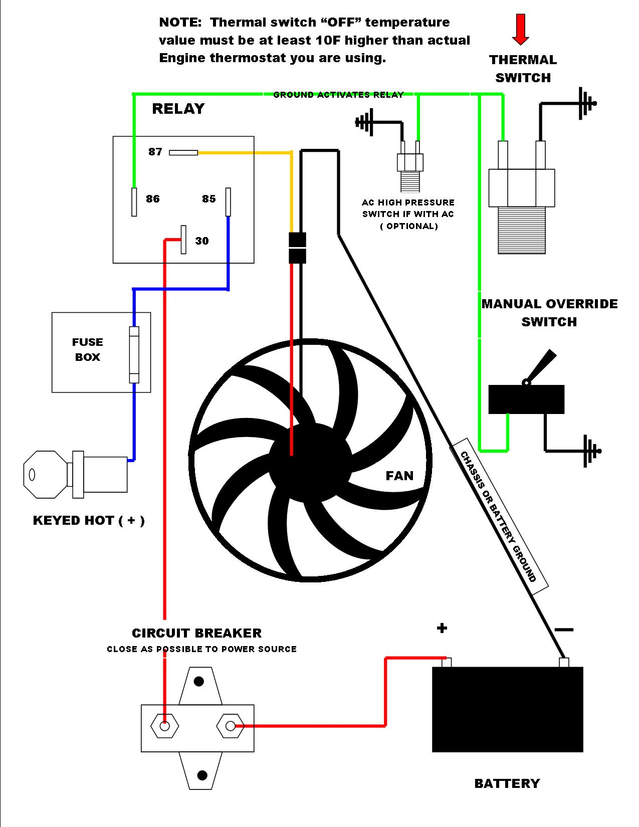
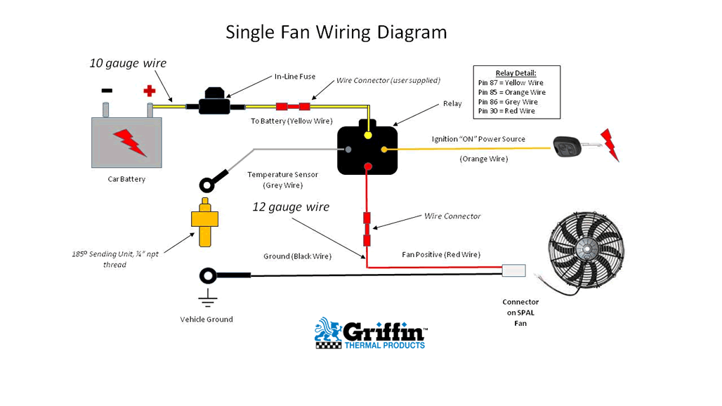
A 30 amp fuse is included, but in single fan applications use the lowest fuse per the current draw. The probe should fit tightly in the radiator fins and should not extend.
Ford Mustang Electric Cooling Fan Wiring Diagrams Wiring Forums

If the fan is not turning in the right direction, air will be blown away from the radiator, and.
Radiator fan switch wiring diagram. I am a little confused about fuse #5 which Switch ignition switch yellow wire to + 12 volts orange wire black wire red wire holder fuse. The gray wire from the a/c relay goes to the +12 volt of the a/c compressor clutch wire.
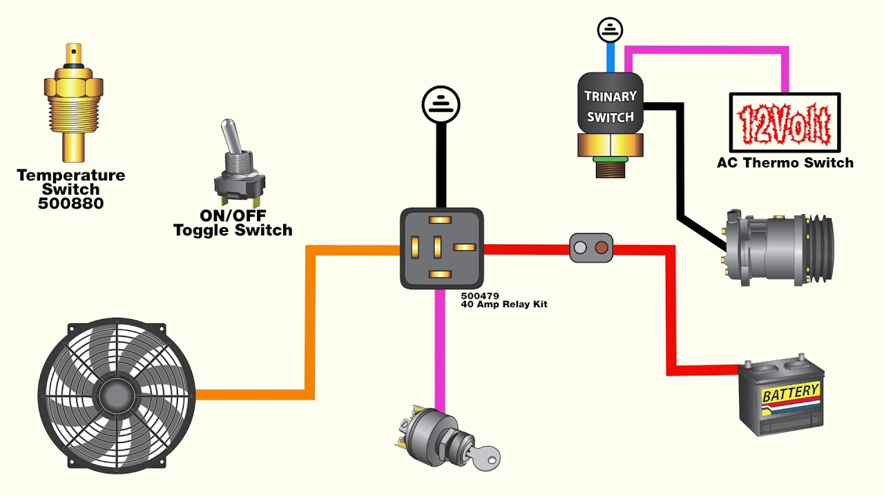
The fan will turn on when the a/c compressor activates. After switching off the a/c, the fans still stay on because of the jumper. Attach positive blue fan wire to pin 87a on the relay.
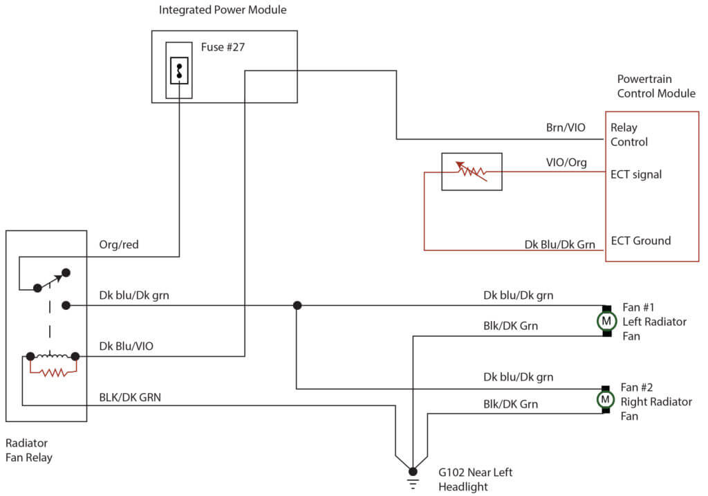
Fan wiring harness with relay and fuse holder fan thermostat 185 degrees 195 degrees overview. The above typical radiator fan circuit wiring diagram applies only to the 2001 2002 2003 and 2004 2 4l dohc chrysler sebring and 2 4l dohc dodge stratus. Reference diagrams 7 8 on page 3 the electric fan assembly is built using a high output two speed motor.
Using a trinary switch can improve system performance, extend the life of the radiator fan, and in this case simplify the wiring substantially. Radiator fan with a/c, without fan pressure switch with positive switched compressor ta9000969 _rev2 101810 page 3 of 4. The electric cooling fans are designed to force air through the core of a heat exchanger, i.e.:
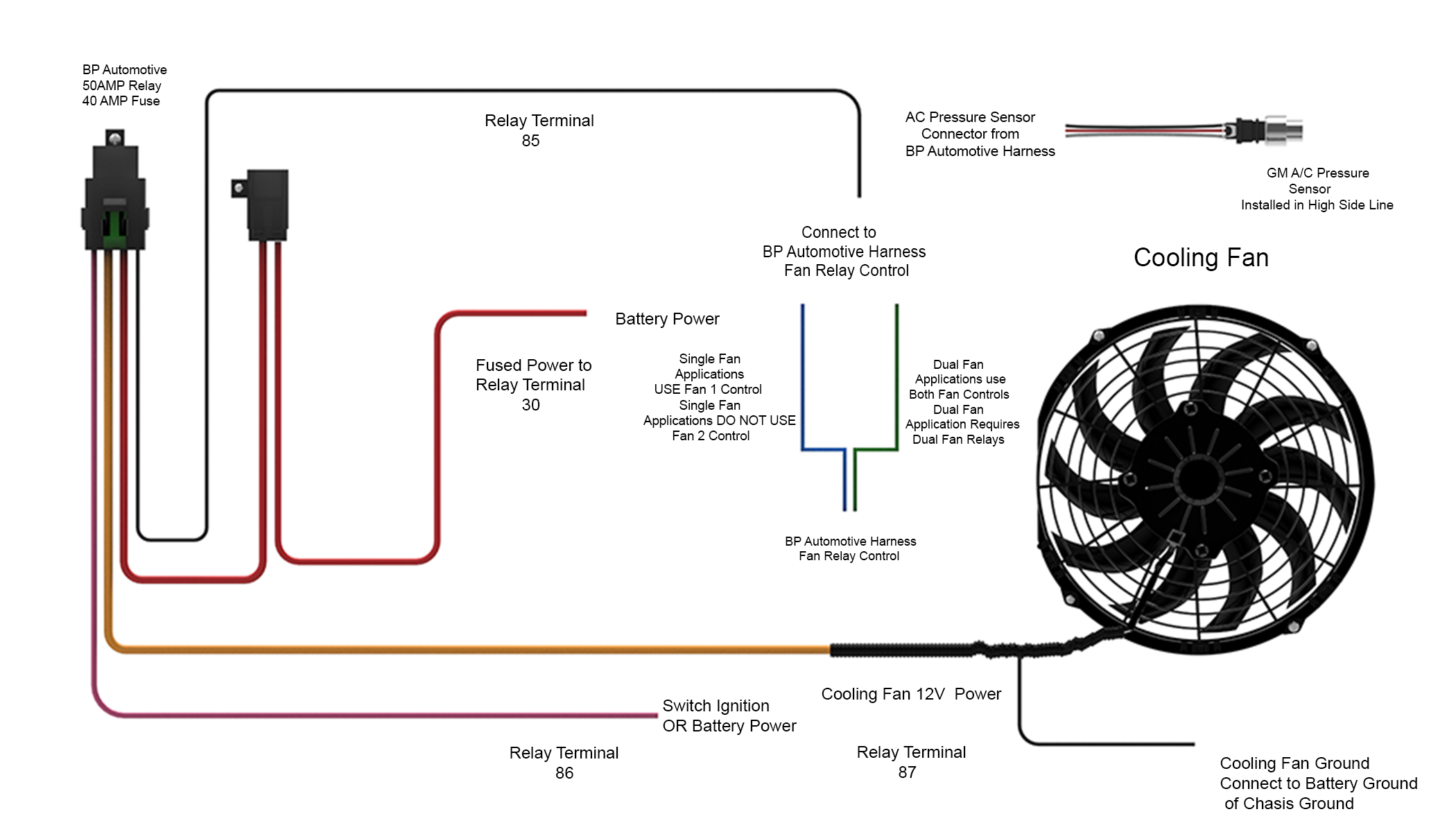
Any ideas of what could be the issue. Head which grounds the dark green/white wire from the auxiliary fan relay (see diagram for location). A northern radiator fan relay kit can be installed for any single or dual fan application up to 40 amp max combined to protect the vehicle wiring and electronics.
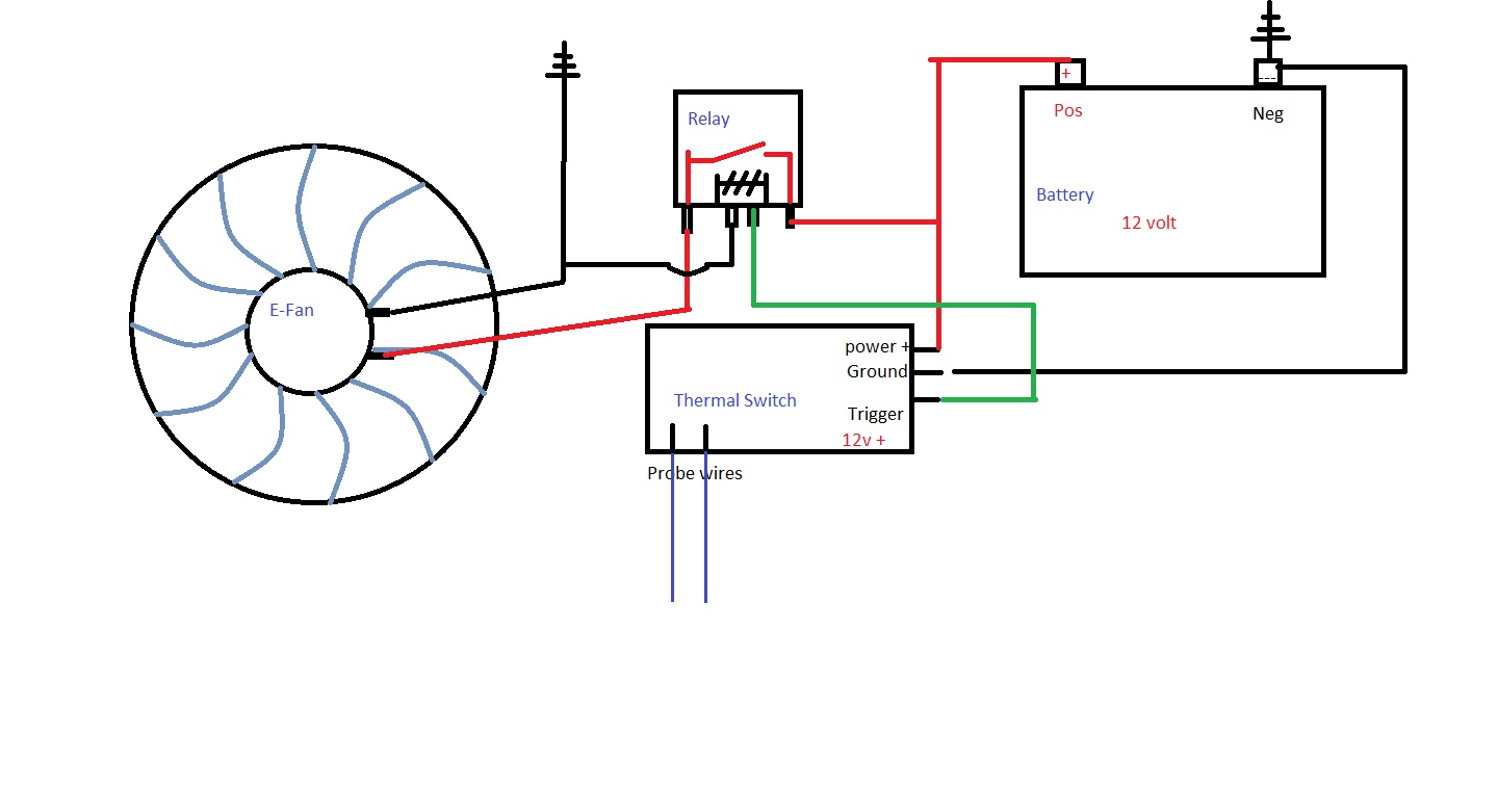
Fan wire chassis ground diagram #7 thermostat switch mounting 1. Wire of the original fan relay harness. It does so based on the temperature information it receives from either your car’s electronic control module or a thermostatically controlled sensor.
Simplest way is to piggyback off the two wires on the radiator thermo switch (big brass bung with two wires in the top of the radiator), bring them both back to the dash and connect to the existong fan switch. Suggested electric fan wiring diagrams converting a 12 volt switch into a ground switch these diagrams show the use of relays, on/off sensors, on/off switches and on/off fan controllers. Some prefer to have the second fan on a manual switch for additional emergency cooling, while others will wire their second fan to use the air conditioning compressor signal to engage the second fan.
Ac gear motor wiring diagram & 4 wire ac motor wiring diagram. Radiator fan with a/c with fan pressure switch. How to wire electric fans a toggle switch.
I looked at the wiring diagrams and everything seems to be connected in the right order. A cooling fan relay controls when the electric radiator cooling fan turns on and off. Connect to (+) power supply within 12” of the battery.
Insert sensor bulb, bend the sensor bulb tube around the end of the radiator inlet. Attach negative fan wire to ground. Two fans with a/c, without fan pressure switch.
When installing an auxiliary fan or simply wiring the factory fan so that the driver can manually turn the fan on and off, make sure the fan is turning in the right direction. All in all, the fans only will come on a operate when i switch the a/c switch. Gray wire to electric fan temp.
The thermal switch has 3/8” pipe thread. It includes the following circuits. Cooling fan wiring diagram a cooling fan relay controls when the electric radiator cooling fan turns on and off.
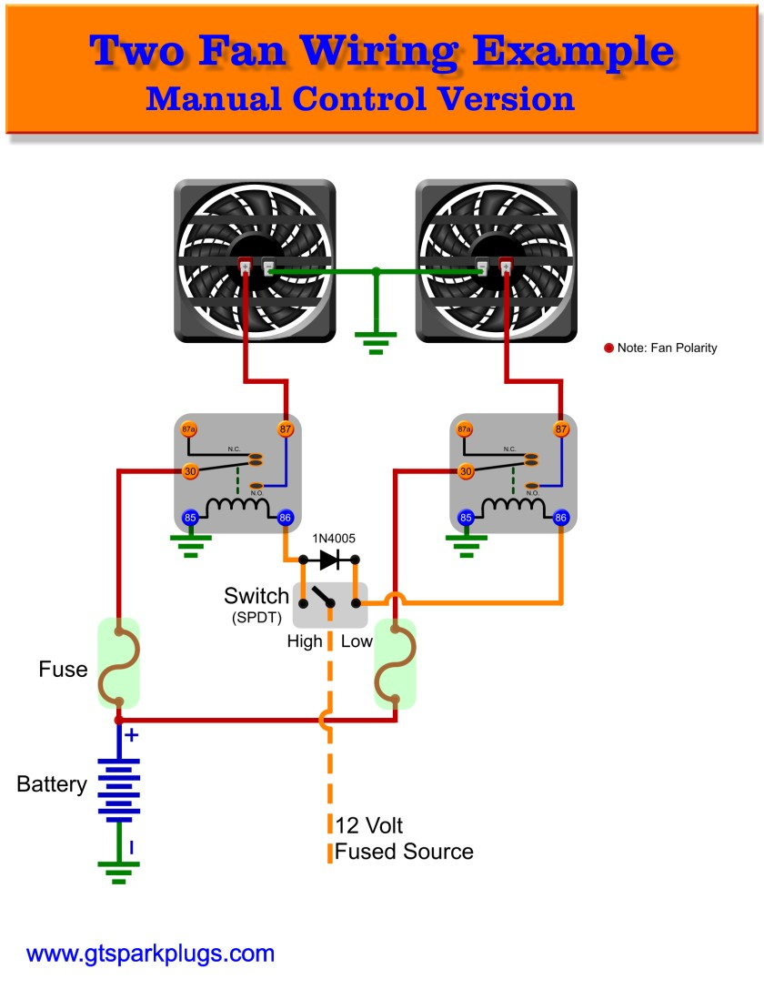
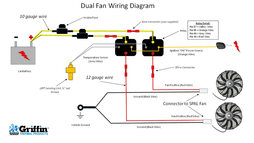
Start your wiring project by taking both of the positive wires from the fans and run them to the yellow wires on each relay (tab 87). Locate the thermostat switch in an accessible location near the radiator inlet hose. Wire a toggle switch to radiator fan wire a toggle switch to radiator fan electric fan with an ac trinary switch jeep cherokee 1984 2001 how to install.
Page 5 12v switched wire to green wire at. Now take the power wire from your fan and connect it to the wire that is going through the firewall. Just an idea on how to wire up electric cooling fans for your vehiclecooling fans:
Connect the c post to pin 85 on the relay. Radiator fan switch wiring diagram. For manual switch installation always follow.
On my old d17 fan switch (coolant temp switch) was mounted in the thermostat housing and not the radiator but the switch is identical to the k series switch and mounts into the radiator the same. You ought to know where your fan relay is even before looking at wiring diagrams so you know where to start. There are three big terminals on it, with the fan they are 12v supply to the switch and then slow and fast to the fan, you want to use.
As past any electrical wiring, make positive every wire connections are made securely later than the proper size wire nuts, that they are not drifting and that no copper strands are showing. The auxiliary fan thermal switch is located in the left cylinder head between the #1 and #3 spark plugs. Next, splice together both black wires from the relays (tab 85) and connect them to the thermostat switch.
A wiring diagram is a simplified traditional pictorial depiction of an electric circuit. The capillary tube probe cannot be lengthened or cut in any way. This is based on the draw from the fans, if the fans are larger and draw more than 15 amps each, it's recommended to install a second relay kit as shown below.
With dual cooling fans, there are two methods for wiring up the relay kit. A wiring diagram usually gives instruction approximately the relative outlook and contract of. This method requires a second temperature switch, a little additional wiring, and of course dual relays.
Suggested electric fan wiring diagrams converting a 12 volt switch into a ground switch these diagrams show the use of relays on off sensors on off switches and on off fan controllers. Connect to the butt connector on the fuse holder wire,. Loosen upper radiator hose at the radiator, pull the hose off the radiator inlet pipe.
Then connect switched power (usually from your ignition switch), to the blue wires on both relays (tab 86).
electricfanwiringdiagramAlsohereisthewiringdiagramIusedforwiringtheelectricfanI

Fan Relay Wiring Diagram Wiring Diagrams Hubs Electric Radiator Fan Wiring Diagram Wiring
Radiator fan switch wiring diagram
Dual Fan Wiring Diagram
Radiator fan switch wiring diagram

Single Fan Wiring Diagram
Electric Radiator Fan Wiring Diagram Cadician's Blog
35 Awesome Electric Radiator Fan Wiring Diagram
Flex A Lite Electric Fan Wiring Diagram Download

Wiring Diagram Electrical. Wiring Diagram Electrical. Radiator fan, Electric cooling fan

35 Awesome Radiator Fan Relay Wiring Diagram
Radiator Fan Wiring Wiring Diagram Data Cooling Fan Relay Wiring Diagram Cadician's Blog
Radiator fan switch wiring diagram
Dual Cooling Fan Wiring Diagram Electric cooling fan, Radiator fan, Automotive electrical

Electric Radiator Fan Wiring Diagram Wiring Diagram And Schematic Diagram Images

Universal Radiator Fan Wiring schematic and wiring diagram

Cooling fan circuit 1 Car mechanic, Electricity, Electric car

Electric Cooling Fan FAQ
Dodge Radiator Fan Wiring Diagram — Ricks Free Auto Repair Advice Ricks Free Auto Repair Advice