Inertia Switch Wiring Diagram
I wouldn’t leave it that way, that. One carries voltage to inertia switch, the other circuit carries voltage from switch.
Irate e fuel install help Page 3 PowerStrokeNation Ford Powerstroke Diesel Forum

From the fsm and wiring diagram i also learned that the factory fuel pump in my car was controlled by the fuel injection relay, which had been deleted long ago from my car.

Inertia switch wiring diagram. The connectors on these switches, due to. From the fuel inertia switch to the fuel pump. The inertia switch is supplied by the fuel pump relay it should be a dk/grn/yell wire going to switch with a pinkblk going out.
Ford inertia switch wiring diagram wiring diagram. Running a 91 mustang computer. Attach the ground wire near the fuse panel to the frame.
Ford inertia switch wiring diagram. It has a red reset switch on it. Look at the switch and find the labels nc and c (diagram b).
Output was 160hp and 225 ft·lbf. Mine is in the trigger wire to the relay. I looked at your wiring diagram, two wires at inertia switch.
You could use jumper wire around the inertia switch, just for testing. I did a search but am not coming up with much. They operate a relay with the inertia switch.
No power to fuel pump checked inertia switch 3 wires going. This video is about check the inertia switch on ford vehicle fuel systems. I checked the wiring diagram i have for a '90 ford.
But, according to the posts i have read there are three different ways of wiring it. Wire to the inertia switch. Higginbotham on thursday, february 14th, 2019 in category wiring diagram.
Look for 12 volts at the pink/black wire (power source for fuel pump relay). Put the switch connector partially onto the switch so you can identify the wires that go to nc and c poles in the switch. (pic shown of module/pump.) it cold be a bad module.
The red wire is voltage from inertia switch, the inertia switch may be faulty. The normally open contact closes. A good wiring diagram has to communicate information quickly clearly and with a.
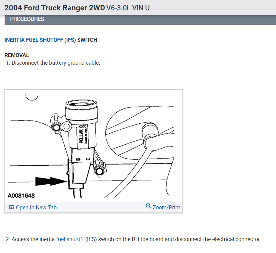
The fuel gauge yellow/white wire and the black/orange wires are saved from the fuel tank harness for the new traction pack capacity indicator. It is located on the passenger side floor, at the front of the carpeting/floor mat near the firewall. At the fuel inertia switch in the kick panel, power from the relay is the dark green w/ yellow stripe wire and the pink w/ black stripe wire is the power.
If you jumper the fuel pump relay, you should hear it run. 2008 ford escape wiring fuel wiring diagram. I still have not wired mine.
Ford windstar fuel pump wiring diagram ricks free auto. Automotive aftermarket manufacturer that designs and build. Fuel pump circuit wiring diagram.
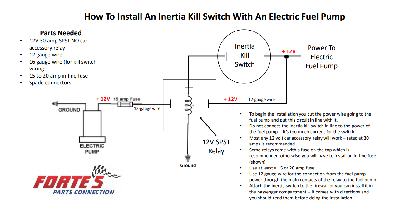
Cut the wire to the fuel pump at a suitable location and strip both ends of the wire (approximately 10mm). That goes to a module that then powers the pump. The sticky relay is a valid point but in my experience with efi fords the relays usually stick in the off position!!!!
Trigger relay, pump ground, and full power or pump positive. Fuel pump relay, fuel pump inertia switch, fuel pump circuits. 0cb8 wiring diagram fuel pump who the equivalent wiring.
The inertia switch pink/black wire is saved from the fuel tank harness. Fuel pump relay, fuel pump inertia switch, fuel pump circuits. Starting circuit kenworth wiring diagram simple switch tunel pump relay inertia gage tunel starter connector image source.
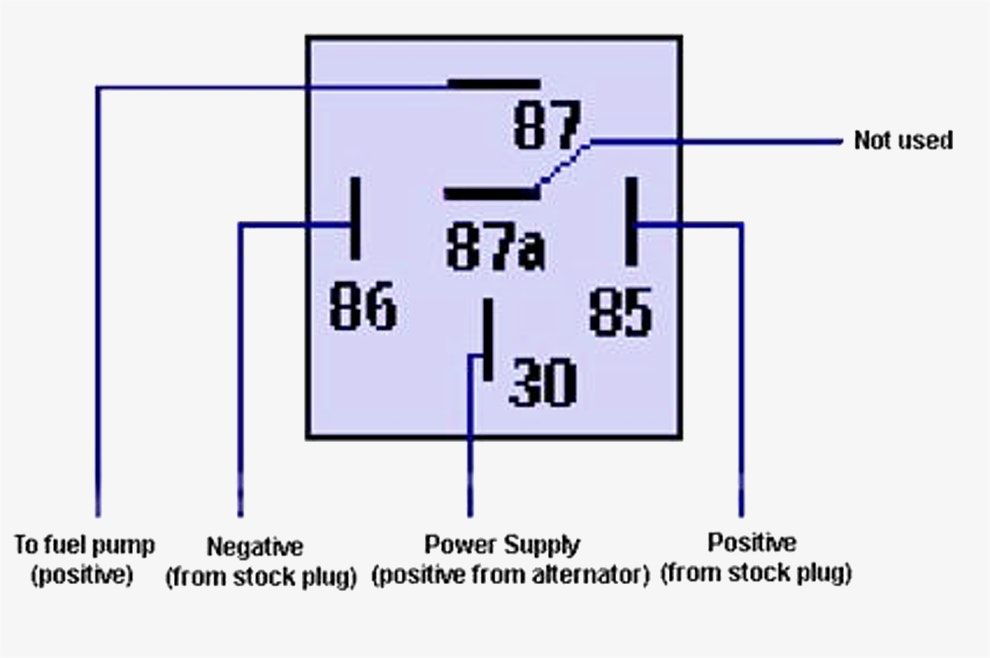
The fuel inertia switch to the fuel pump itself. Push the inertia switch down to make sure it is “on” harness ground make sure that any coating on the frame is removed before attaching grounds so that a good contact is made. One will be used exactly like the basic wiring diagram (terminal 1 and 3).
3 way switch wiring diagram with line and load in the same switch box. 28 inertia diagram inertia system inertia diagram. Does anyone have a diagram on how to wire this in or can tell me that would be great.
The other side of the inertia switch with the brown\pink wire joins the pink/black wire that connects to the fuel pump. The voltage reading on both should be the same. Using the connectors provided, join the nc wire (to pump) and
In the above diagram the white wire must be re identified as a hot wire at each switch location. Requiring a nice hard rap to get them to work! The switch actually is 2 switches in one.
The fuel pump has a black wire that supplies the ground to complete the circuit. The 4.0l ohv engine was produced until 2000 and was used in the ford explorer and ranger. This is where you wire to the pump ( you should actually use a relay as the inertia switch is probably not designed for high current long term use) if the switch is tripped then the nc goes open killing the power.
These electrical and electronic circuit symbols are generally used for drawing schematic diagram. From the fsm and wiring diagram i also learned that the factory fuel pump in my car was controlled by the fuel injection relay, which had been deleted long ago from my car. Either drill a hole, remove any frame coating from the
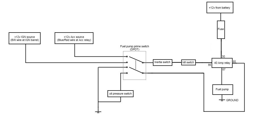
Fancy your knowledge when it comes to ford engines? The extra terminal (terminal 2) will close to ground (via engine block typically and body of the switch) when pressure is lower than a couple of psi, and will open when the engine is making oil pressure just like the old idiot lights! The generator fault light wire light green/red is saved from the alternator harness for the new run indicator.
Going to add the stock ford inertia switch with the efi conversion. Here we have another image ford escape. Airtex is the only u.s.
This is a newer switch so it is equipped with the no switch to light a bulb in the dash to alert. If the inertia switch is triggered, the relay turns off, turning off the pump.
Is there eneything between the inertia switch and the fuel pump on a 2002 ford 350 7.3 diesel I

Is my inertia switch suppose to have 3 wires? Yahoo Answers

Where is the inertia switch located on a 1995 mazda 626?

How To Bypass Inertia Switch On A Ford Probe GT?

Electric fuel pump wiring an inertia switch Page 2 Ford Truck Enthusiasts Forums
Ford Inertia Switch Wiring Diagram For Your Needs
Ford Inertia Switch Wiring Diagram CIKERI
Inertia Switch Forte's Parts Connection
20 Fresh Inertia Switch Wiring Diagram
20 Fresh Inertia Switch Wiring Diagram
No power to fuel pump checked inertia switch 3 wires going to it yellow and pink then a skinny

Electric Fuel Pump Wiring Diagram

Ford Inertia Switch Wiring Diagram Images Wiring Diagram Sample

[ IMG]
Where is the inertia switch on a 2005 chevy Aveo Sedan

Ford Inertia Switch Wiring Diagram For Your Needs

Ford Inertia Switch Wiring Diagram For Your Needs
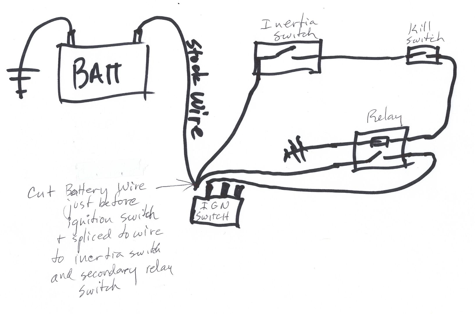
Emergency Kill Switch The Ford Barn
20 Unique Ford Inertia Switch Wiring Diagram